
Inductors are devices that store electrical potential energy in a magnetic field. They are constructed by coiling wire and significantly enhanced by placing ferrous material in the middle of the coil.
Inductor Symbol

Common Inductor Equations

The Voltage through an inductor equals the inductance times the rate of change of current (time derivative of current).
This equation means a couple important things:
- Current through an inductor cannot change instantaneously, to do that would require an infinite voltage. Inductors fight against rapid changes in current.
- Voltage across an Inductor is proportional to the rate of change of current through the inductor. The constant of proportionality is the Inductance.
- Voltage across and Inductor can change instantaneously.

An inductor’s Reactance = 2 * Pi * Frequency in Hz * Inductance; Reactance has units of Ohms
- Reactance for an inductor increases as frequency increases. Inductors act as open circuits to high-frequency signals and act as short circuits to low-frequency signals.
- Positive reactance means that voltage leads current (voltage changes quickly, current lags behind)
- For an ideal inductor, its resistance is 0, so its impedance is ZL = R + jXc = j * (2πfL)
Ideal Inductor:  ; f = frequency in Hz, L = inductance, j = imaginary number
Right-Hand Rule
In order to understand why coiling wire creates an inductor, you need to learn about the right-hand rule.
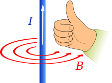
The Right-Hand Rule says that if you place your right hand with thumb in direction of current the magnetic field will be in the direction of you fingers that curl about the axis of your thumb. So, now imagine a coiled wire. Imagine current flowing through that wire in a particular direction, and then imagine the magnetic field formed by current flowing through each loop of wire. The magnetic field on the inside of each loop goes one diection, and the magnetic field on the outside of each loop goes the opposite direction. The magnetic field from each loop adds into an overall magnetic field.
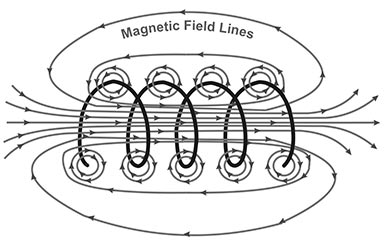
When you place ferrous material, called a ferrite core, in the middle of coiled wire, the magnetic field interacts with the ferrite core and is boosted significantly.
Key Specifications of Real Inductors
- Inductance
- Tolerance – accuracy of the inductance
- Current Rating – There are two types of current ratings for inductors. One is the current rating due to heat created, the other is current above which the ferrite core will become saturated with magnetic field and the inductor starts loosing inductance rapidly. You do not ever want the core to become saturated.
Types of Inductors
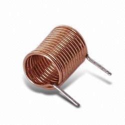
Air Core Inductors
- Do not use ferrite material in the core of the coil. Instead, ceramic material is used in the core to provide mechanical structure.
- Have relatively low inductance
- Typically used for high-frequency applications
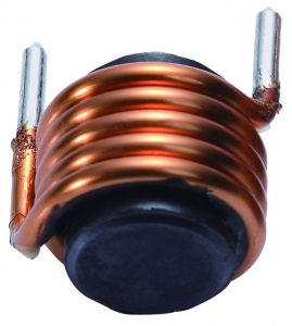
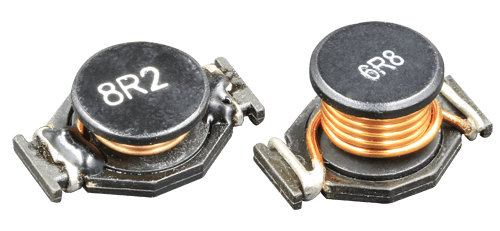
Ferrite Core Inductors
- Much higher inductance than air core inductors
- Higher cost due to the ferrite material
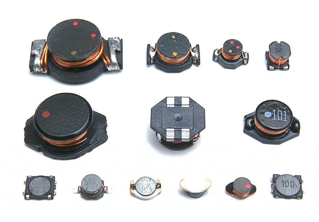
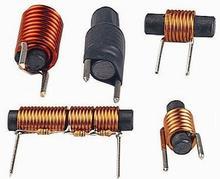
Shapes of Ferrite Core Inductors
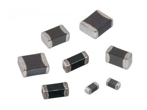
Chip Inductors
- Surface Mount Devices (SMD)
- Small sizes available using same package dimensions as SMD resistors
- Relatively low inductance and low current rating
- Typically used for Radio Frequency (RF) and other high-frequency filters
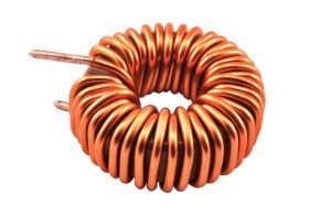
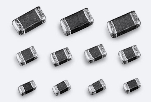
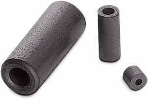
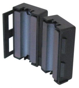
Ferrite Beads & Cores
- Also called ferrite chokes
- Available in small SMD packages for placing in series with a signal or in larger sizes that go around cables
- Their electromagnetic effect is not quite the same as a true inductor. They become more resistive to higher frequency signals.
- Less expensive than inductors
- Used mainly for filtering noise out of power lines and for filtering noise out of cables to reduce conducted and radiated emissions.
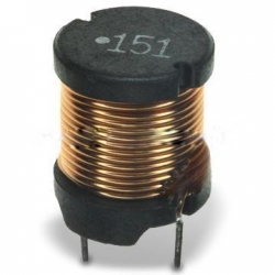
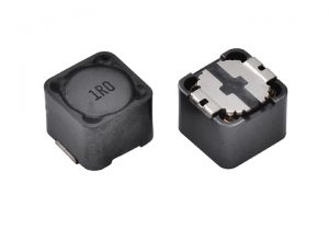
Shielded Inductors
- Shielded inductors have ferrite material surounding the coiled wire, which keeps much of the magnetic field inside the device.
- Shielded inductors are more expensive than non-shielded.
- Shielded inductors have a number of uses:
- Use when you have to place inductors close together to avoid them acting like transformers.
- Use when you have to place an inductor near sensitive signals
- Use to reduce radiated emissions from the inductor
Common Inductor Values
| Standard Inductor Values | |||
| nH, µH | nH, µH | nH, µH | nH, µH |
| 1.0 | 10 | 100 | 1000 |
| 1.1 | 11 | 110 | 1100 |
| 1.2 | 12 | 120 | 1200 |
| 1.3 | 13 | 130 | 1300 |
| 1.5 | 15 | 150 | 1500 |
| 1.6 | 16 | 160 | 1600 |
| 1.8 | 18 | 180 | 1800 |
| 2.0 | 20 | 200 | 2000 |
| 2.2 | 22 | 220 | 2200 |
| 2.4 | 24 | 240 | 2400 |
| 2.7 | 27 | 270 | 2700 |
| 3.0 | 30 | 300 | 3000 |
| 3.3 | 33 | 330 | 3300 |
| 3.6 | 36 | 360 | 3600 |
| 3.9 | 39 | 390 | 3900 |
| 4.3 | 43 | 430 | 4300 |
| 4.7 | 47 | 470 | 4700 |
| 5.1 | 51 | 510 | 5100 |
| 5.6 | 56 | 560 | 5600 |
| 6.2 | 62 | 620 | 6200 |
| 6.8 | 68 | 680 | 6800 |
| 7.5 | 75 | 750 | 7500 |
| 8.2 | 82 | 820 | 8200 |
| 8.7 | 87 | 870 | 8700 |
| 9.1 | 91 | 910 | 9100 |
Helpful Videos
Next: Diodes