
When prototype PCAs are received from the fabricator, electrical engineer(s) will check the boards and run an initial set of tests. This process is called Bringup. When you are waiting for PCAs to be fabricated, it is a good practice to think through the bringup process and document a bringup plan. Each process will be different as it needs to be tailored to the functionality of the PCA, but in general bringup is the process of starting up and briefly checking each major piece of functionality. The goal is to verify that enough functionality is working to allow other disciplines to start testing and developing with the PCA and to allow EEs to move on to more extensive testing.
As an example, I will outline the bringup process I would use for a PCA containing an embedded computer system. I think this process is extensible to many other types of circuit boards.
Bringup Process – Embedded Computer
- Visual Inspection
- Measure resistance of each power rail to ground; verify no short
- Apply Power; touch each major component and verify not too hot
- Measure the voltage of each power rail; verify correct voltage of each rail
- Measure the state of the reset signal(s); verify reset is released
- Toggle power and measure data or some signal to non-volatile memory (Flash); verify processor is attempting to fetch code.
- Connect debug probe to processor; verify processor is identified and you can communicate
- Use processor probe or firmware to have processor write and read RAM
- Use sample code or custom firmware to turn on and check each I/O port such as RS232, USB, ethernet.
- Enable and check each other major piece of functionality on the PCA such as sensors, motor drivers, buttons, etc.
- Bringup complete
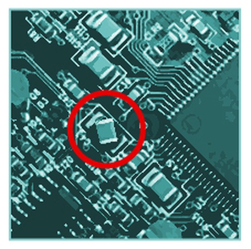
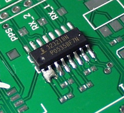
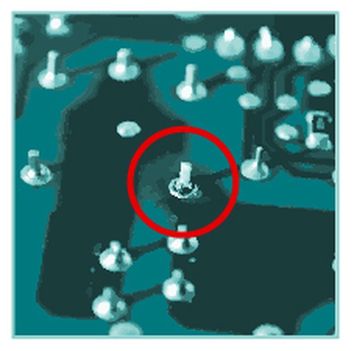
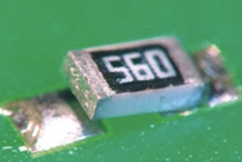
Visual Inspection
The first step of bringup is to perform a thorough inspection of a PCA. Use a magnifier to see small details and look over both sides of the board in a methodical manner. Here are some things to look for during the inspection:
- Expected markings are present and correct (country of origin, part number, etc.)
- Check orientation of polarized capacitors
- Check orientation of chips (pin 1 is in the right place)
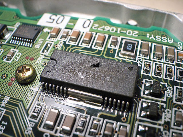
- Look for holes in chip packages
- Look for twisted components
- Look for obvious solder bridges
- Look for insufficient barrel-fill for through pins
- Look for tilted components (tombstoning)
- Components loaded and no-loaded correctly
Checking Power
After performing the visual inspection, before applying power, check each voltage power rail on the board to make sure it is not shorted to ground. Use an Ohmmeter to measure resistance of each rail to ground with the board powered off. Resistance can be quite low under normal circumstances, depending on what type and amount of circuitry is powered by that rail. Measuring 20, 25 Ohms probably should not be alarming, but if you measure something like 5 Ohms or less, you should suspect and investigate a short.
If you don’t measure a short, then it is time for the moment of truth, when you apply power. Be aware that the sucker can explode. It really can. More specifically, polarized capacitors that are loaded backwards can blow up when powered. Other components can melt down and smoke, and fire can erupt. One strategy is to locate a technician and ask them to “help” you with this project. Then, stand behind that technician. No, I’m just kidding. The explosions and fires and so forth are not that big, usually. Just stand back a bit, maybe put on some protective glasses, and flip the switch.
Once power is applied, touch all the major components lightly to feel for ones that are getting too hot. Also, feel the PCB for hot areas. If something is getting too hot, kill the power. Look at the illumination state of any LEDs on the board to see what they indicate.
Next, measure the voltage of each power rail to see if it is close to the expected value. Use an oscilloscope for this, so you can also see if the rail looks stable or is oscillating or really noisy; a multimeter will not show those problems. If the voltages look good, move on to measuring the logic state of the reset signals. (If a board has digital circuitry, it has reset.) If the board is stuck in reset, look at the schematics and start checking signals to determine what is holding reset asserted.