State machines are electronic devices or software routines that have a number of states and transition between those states based on the values of input signals. Electronic state machines can be asynchronous where the state changes when inputs change or synchronous where the state only changes on rising, falling, or both transitions of a clock signal. Synchronous state machines are the basis for most modern digital electronic systems.
Synchronous electronic state machines can be constructed from D-Flip-Flops, combinatorial logic gates and feedback connections, and I am going to walk through this process. It is not particularly difficult to grasp the process, but the process is fairly long and tedious, and grows exponentially with the number of states of the state machine. As I said before, in practice it is rare to implement a state machine with discrete parts, but rather a programmable logic device would be used, or it would be implemented in software. A programming language is is used describe the logic in a programmable logic device, and I will show an example further below.
States Represented by Q Outputs of D-Flip-Flops
A state machine needs something to represent the states. When using D-Flip-Flops the state is represented by the Q output of each flip flop. With two flip-flops we have two Q outputs, and the number of values that can be represented by two binary signals is 2 ^ (number of signals) = 2 ^ 2 = 4. So, up to four states can be represented by two flip-flops. 3 flip-flops can represent up to 2 ^ 3 = 8 states.
State Machine Conceptual Diagram
I’m going to start calling Flip-Flops: FFs.
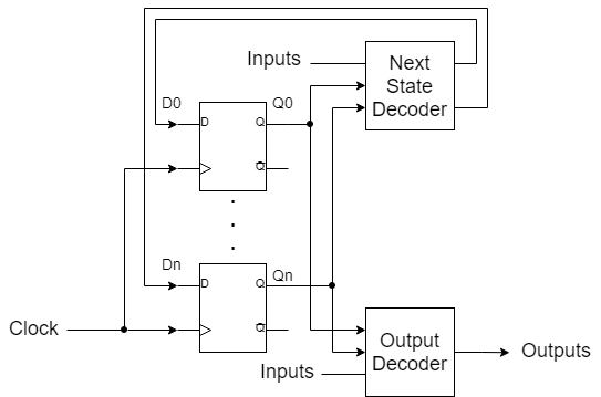
The state machine has 3 main parts: D-FFs, Next State Decoder (NSD), and Output Decoder (OD). The two decoder blocks consist of combinatorial logic, and the D-FFs constitute the synchronous element. And a clock signal drives the state machine, causing it to check whether to transition to another state.
The Next State Decoder determines the next state the machine will change to, and it places that state on the D inputs to the FFs. The Output Decoder takes the current state, represented by the Q outputs of the FFs, as inputs. And, it drives outputs based on those state inputs and other inputs to the state machine. Inputs to the state machine can go to the NSD or to the OD; inputs to the NSD will cause changes to the outputs synchronously (on clock edge); inputs to the OD will cause changes to the outputs asynchronously, because that route bypasses the FFs.
Next State Decoder (NSD): Determines next state the machine will transition to.
Output Decoder (OD): Determines outputs based on inputs and the current state.
Inputs to NSD cause synchronous changes in the outputs
Inputs to the OD cause asynchronous changes in the outputs
Grey Code
I need to insert a topic here that is important for state machines: Grey Code. Grey Code is a way of counting binary where only one digit changes value with each change of count. With two digits, for example, Grey Code counts 00, 01, 11, 10 which is not the same as the standard binary count 00, 01, 10, 11.
Grey Code: 000, 001, 011, 010, 110, 111, 101, 100
So, what does Grey Code have to do with state machines? If successive states that a state machine goes through are numbered in grey code, Next State Decoder logic is simplified, because only one D/Q of the FFs is changing each state change. This is a trick. It is not required. But, it is best to order your states by grey code rather than by binary count.
Grey Code gets is name from encoder strips that appear grey. A quadrature encoder sensor running over an encoder strip outputs a two bit grey code count. We’ll talk about encoders and motion control at some point.
Next: State Machine Example