
Capacitors are devices that store electrical potential energy in an electric field. They are constructed by placing two conductive surfaces in close proximity to each other, but separated by a insulating dielectric material. The more surface area in close proximity and the closeness of that proximity and the type of dielectric material determine the capacitance.
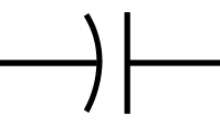
Capacitor Symbols

Common Capacitor Equations
Current/Voltage Relationship: 
The current through a capacitor equals the capacitance times the rate of change of voltage (time derivative of voltage).
This equation means a couple important things:
- Voltage across a capacitor cannot change instantaneously, to do that would require an infinite current. Capacitors fight against rapid changes in voltage.
- Current through a capacitor is proportional to the rate of change of voltage. The constant of proportionality is the Capacitance.
- Current through a capacitor can change instantaneously.
Reactance: 
A capacitor’s reactance = -1 Divided by 2 * Pi * Frequency in Hz * Capacitance; Reactance has units of Ohms
- Reactance for a capacitor decreases as frequency increases. Capacitors act as short circuits to high-frequency signals and act as open circuits to low-frequency signals.
- Negative reactance means that current leads voltage (current changes quickly, voltage lags behind)
- For an ideal capacitor, its resistance is 0, so its impedance is:
Impedance: 
Key Specifications of Real Capacitors
- Capacitance – nominal capacitance
- Tolerance – accuracy of capacitance
- Maximum Voltage
- Loss Tangent or Equivalent Series Resistance – indicates how much resistance the capacitor has
- Ripple Current
Real world capacitors come in a wide range of values and their limiting specification for most applications is their voltage rating. The size of capacitors is related to both capacitance and voltage rating, which is a bit different than resistors whose size is mainly just determined by power rating.
Loss Tangent and ESR
In most capacitor applications, one wants minimum equivalent series resistance (ESR). But, in the case of switching power converters usually some ESR is required in the large output capacitor, and you need to check its rating against the requirements of the regulator. Some capacitor vendor, however, do not specify ESR, but instead specify loss tangent. Why do they do this? To provide you with the exciting opportunity to convert loss tangent to ESR. Here’s how you do it.
The capacitor datasheet will specify loss tangent at a specified frequency. You need both values to convert to ESR.
Loss Tangent to ESR Conversion: 
ESR = [Loss Tangent] divided by the quantity 2 * Pi * [Frequency of the Loss Tangent Specification] * [Capacitance of the Capacitor]
Ripple Current
Types of Capacitors
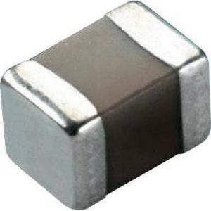
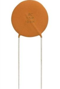
Ceramic Caps
- Not polarized. It does not matter which terminal you connect to positive or negative voltage.
- Combination of capacitance and voltage rating determine the package size.
- Available in surface mount (SMD) style or through-hole lead style.
SMD ceramic capacitors use the same package sizes as SMD resistors, which is down-right considerate of the industry - SMD cermaic caps are very inexpensive, can be very small, have very low parasitic series resistance (ESR) and are the clear choice to use unless you need special characteristics provided by other types.
- The main downside of ceramic capacitors is that they do not have as much capacitance as other types. Capacitance is available up to 100uF.
- Ceramic caps are available with different dielectric types, and dielectric type has a big effect on tolerance. Four of the most common types are listed below.
- C0G: +/-30 ppm/C (30 parts per million per degree Celcius). This is the one to use when you need capacitance accuracy
- X5R: +/- 15% over specified temp range of -55C to +85C
- X7R: +/- 15% over specified temp range of -55C to +125C. X5R and X7R are typically what you want to use.
- Y5V: +22%/-82% over specified temperature range of -30C to +85C. This type is very inaccurate, and I would avoid them.
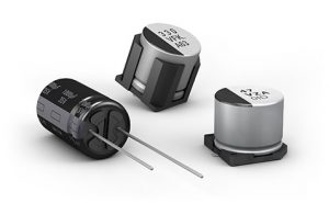
Aluminum Eectrolytic
- Polarized. You have to connect one terminal to positive voltage and one to negative voltage, otherwise it will explode, literally. And yes, I know this from personal experience.
- Hold alot of capacitance and have good voltage ratings
- Downsides: large size, high ESR (note that high ESR is not always a bad thing)
- Better at handling large dynamic currents than other types even though they have high ESR, except compared to ceramic caps.
- Typically used for bulk decoupling capacitance, which keeps voltage power rails steady, and in switching DC:DC power converters where the high ESR is often needed for control stability.
- Aluminum Electrilytic caps have a specified lifespan, which is important. This is specified in hours of operation, and a typical value is 2000 hours. This is a very short time, only 83 days! How can this device be useful then? The answer is that the lifespan is specified for the device at maximum specified temprature and at maximum specified voltage. If you run the device at lower temp or lower voltage, it will last much longer. Basically, if you are designing something that is only intended to last a couple years, then 2000 hour part is fine, if you are designing something to last more like 5, 7, or 10 years, then find a part with longer lifespan spec.
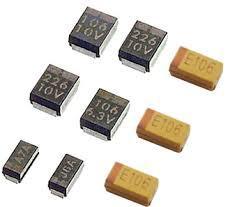
Tantalum Electrolytic Caps
- Provide alot of capacitance in a small size.
- Have low ESR: higher than ceramic caps, but much lower than aluminum-electrolytic
- Relatively expensive
- Be very careful not to exceed voltage or dynamic current specs. Their failure mode is a cascading electrical short with thermal runaway, which is bad, because it can cause fires.
- Frankly, it may be better to use the next type, aluminum polymer caps, which have the same benefits without the catastophic failure mode.
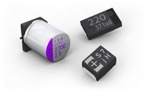
Aluminum Polymer Caps
- Have low ESR and high capacitance in a small package
- Do not have the catastophic failure mode of tantalum caps
- Relatively high cost
- This is the part to use if you need alot of capacitance in a small space.
Common Capacitor Values
| pF | pF | pF | pF | µF | µF | µF | µF | µF | µF |
| 1.0 | 10 | 100 | 1000 | 0.01 | 0.1 | 1.0 | 10 | 100 | 1000 |
| 1.1 | 11 | 110 | 1100 | ||||||
| 1.2 | 12 | 120 | 1200 | ||||||
| 1.3 | 13 | 130 | 1300 | ||||||
| 1.5 | 15 | 150 | 1500 | 0.015 | 0.15 | 1.5 | 15 | 150 | 1500 |
| 1.6 | 16 | 160 | 1600 | ||||||
| 1.8 | 18 | 180 | 1800 | ||||||
| 2.0 | 20 | 200 | 2000 | ||||||
| 2.2 | 22 | 220 | 2200 | 0.022 | 0.22 | 2.2 | 22 | 220 | 2200 |
| 2.4 | 24 | 240 | 2400 | ||||||
| 2.7 | 27 | 270 | 2700 | ||||||
| 3.0 | 30 | 300 | 3000 | ||||||
| 3.3 | 33 | 330 | 3300 | 0.033 | 0.33 | 3.3 | 33 | 330 | 3300 |
| 3.6 | 36 | 360 | 3600 | ||||||
| 3.9 | 39 | 390 | 3900 | ||||||
| 4.3 | 43 | 430 | 4300 | ||||||
| 4.7 | 47 | 470 | 4700 | 0.047 | 0.47 | 4.7 | 47 | 470 | 4700 |
| 5.1 | 51 | 510 | 5100 | ||||||
| 5.6 | 56 | 560 | 5600 | ||||||
| 6.2 | 62 | 620 | 6200 | ||||||
| 6.8 | 68 | 680 | 6800 | 0.068 | 0.68 | 6.8 | 68 | 680 | 6800 |
| 7.5 | 75 | 750 | 7500 | ||||||
| 8.2 | 82 | 820 | 8200 | ||||||
| 9.1 | 91 | 910 | 9100 |
Capacitor Voltage Ratings
| Ceramic | Electrolytic | Tantalum | Mylar (Polyester) |
Mylar (Metal Film) |
| 10V | 10V | |||
| 16V | 16V | 16V | ||
| 20V | ||||
| 25V | 25V | 25V | ||
| 35V | 35V | |||
| 50V | 50V | 50V | 50V | |
| 63V | ||||
| 100V | 100V | 100V | ||
| 160V | ||||
| 200V | ||||
| 250V | 250V | |||
| 350V | ||||
| 400V | 400V | |||
| 450V | ||||
| 600V | ||||
| 630V | ||||
| 1000V |
Ceramic Capacitor 3-Letter Codes
Class I Caps
| First character | Second character | Third character | |||
|---|---|---|---|---|---|
| Letter | Sig Figs* | Digit | Multiplier 10x | Letter | Tolerance |
| C | 0.0 | 0 | -1 | G | +/-30 |
| B | 0.3 | 1 | -10 | H | +/-60 |
| L | 0.8 | 2 | -100 | J | +/-120 |
| A | 0.9 | 3 | -1000 | K | +/-250 |
| M | 1.0 | 4 | +1 | L | +/-500 |
| P | 1.5 | 6 | +10 | M | +/-1000 |
| R | 2.2 | 7 | +100 | N | +/-2500 |
| S | 3.3 | 8 | +1000 | ||
| T | 4.7 | ||||
| V | 5.6 | ||||
| U | 7.5 | ||||
Class II Caps
| First character | Second character | Third character | |||
|---|---|---|---|---|---|
| Letter | Low Temp | Digit | High Temp | Letter | Change |
| X | -55C (-67F) | 2 | +45C (+113F) | D | +/-3.3% |
| Y | -30C (-22F) | 4 | +65 (+149F) | E | +/-4.7% |
| Z | +10C (+50F) | 5 | +85 (+185F) | F | +/-7.5% |
| 6 | +105 (+221F) | P | +/-10% | ||
| 7 | +125 (+257F) | R | +/-15% | ||
| S | +/-22% | ||||
| T | +22% / -33% | ||||
| U | +22% / -56% | ||||
| V | +22% / -82% | ||||
Helpful Videos
Next: Inductors