
Phase Locked Loops (PLLs) are feedback control circuits that lock on to the frequency and phase of the input signal and produce an output signal with frequency and phase that is proportional to that of the input. Below is a block diagram of an analog PLL based on a device called a charge pump, which can generate a voltage level (VCTRL) that is proportional to its input signal (E(s)).
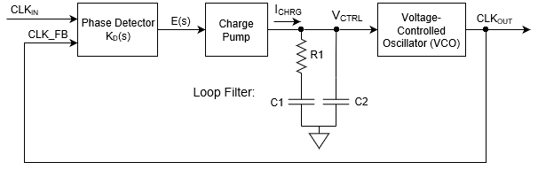
The Phase Detector compares its two inputs the input clock signal CLKIN and the feedback signal CLKFB and outputs a signal that is proportional to the difference. This signal is the Error signal E(s), which drives the charge pump. The output of the charge pump VCTRL is filtered by the Loop Filter to remove unwanted frequency components, and drives the Voltage-Controlled Oscillator (VCO). The VCO generates an oscillating signal output whose frequency is proportional to its input, and the output of the VCO is the output of the PLL and is the feedback signal for the Phase Detector.

Applications
- Frequency Modulation (FM) and demodulation. Used to lock on to radio station carrier waves, for example.
- Frequency Synthesis – Produce clock signals with different but proportional frequencies from a master clock signal. The master clock and derived clocks all share a phase relationship.
- Clock recovery – Recover the clock signal from a serial stream of data that is encoded to enable clock recovery.
- Jitter reduction – Reduce noise in the periodicity of a signal making the edges occur on a more regular cadence.
- Spread spectrum clocking – Slew the frequency of a clock around a bit to reduce and spread out the associated spectral peak, which reduces electromagnetic interference.