
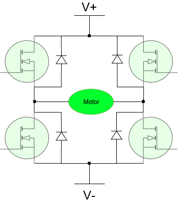
H-Bridges consist of four power transistors connected in a manner the resembles an “H”. Its purpose is to drive power to an inductive load with changeable polarity. The load connected as the horizontal bar in the “H” formation.
The most common application of an H-Bridge is to drive a Brushed DC Motor, which is an inductive load. Changing the polarity of drive changes the direction the motor spins, and H-Bridges can do this by turning on and off different pairs of transistors. Power delivered to the motor can also be controlled by the H-Bridge using pulse width modulation (PWM), but let’s talk about the basics first. Let’s look at the circuit model of a brushed DC motor.

A Brushed DC Motor is modeled with a resistor in series with an inductor, which is in series with a voltage generator. A voltage generator??? Yes, when the motor is driving a mechanical load that has significant momentum, and you stop driving current through the motor, that big heavy spinning thing will keep the shaft moving past the coils, which actually generates a voltage. The polarity of this generated voltage is always such that it causes current to flow back against the direction current was flowing to drive the motor. It flows back into the positive terminal of the power source. This phenomenon is called Back EMF (Electro-Motive Force).
Back EMF: Voltage opposing the direction of drive current that is generated by magnetic induction from the momentum of the mechanical load
Equipped with the brushed DC motor circuit model, let’s look at how it can be driven by an H-Bridge. The H-Bridge is operated by turning on and off pairs of transistors.
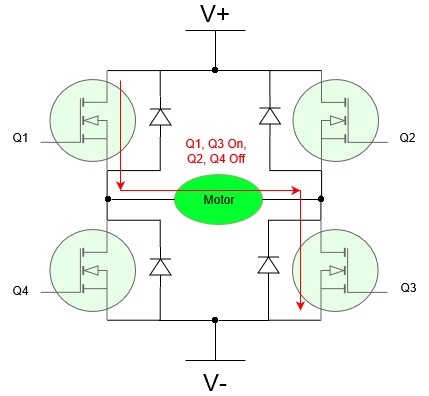
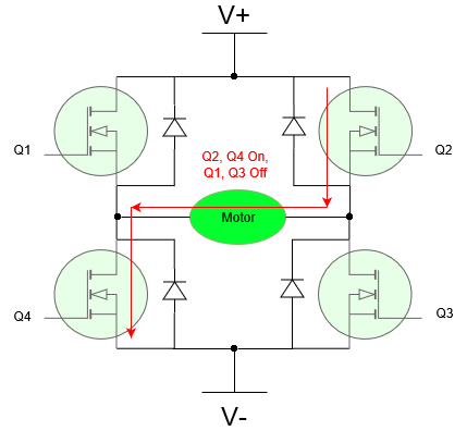
Ignore the diodes for the moment and refer to the diagram on the left. Turning on transistors Q1 and Q3 causes current to flow from the positive terminal of the power supply V+, through Q1, through the motor left-to-right, through Q3, to the negative terminal V-. By turning off Q1 and Q3, and turning on Q2 and Q4, current flows through Q2 and Q4 and the opposite direction through the motor.
When voltage is applied across the motor by the bridge, the motor initially appears as an open circuit with high impedance due to the discharged inductor in its circuit model. Current ramps up exponentially until the inductor reaches steady-state.
Remember that inductors give momentum to current; current through an inductor cannot be shut off abruptly. So, when a motor is being driven and then the H-Bridge transistors turn off, current will continue to flow one way or another, and it is best if we provide a path. This is the purpose of the diodes. There is always a path for current to continue flowing through pairs of diodes even if all the transistors are turned off.
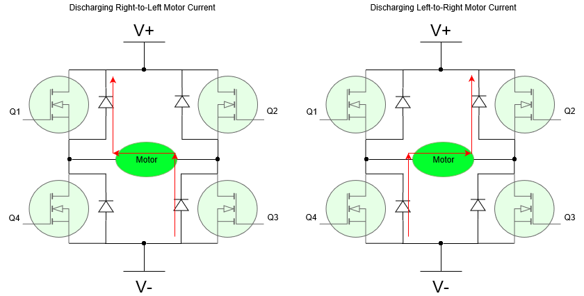
The diodes in an H-Bridge often come as part of the FET transistor. Many power MOSFETs have a Body Diode that serves this purpose.