
Mutual Inductance
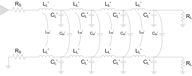
Before we get to the topic of crosstalk, we need to introduce the concepts of mutual inductance and mutual capacitance. Remember that changing magnetic fields create an electromotive force (voltage), and if a conductor is present within the changing fields, the voltage induces a current to flow in that conductor. Changing currents flowing around a loop such as a trace suspended over a reference plane for return current, produce changing magnetic fields, and if a trace is nearby induced voltage will cause a current to flow in it. This is called mutual inductance, and the effect is increased with higher frequency.

- VV = Voltage induced in the victim trace
- LM = Mutual inductance
- IA = Current in the aggressor trace
Let’s talk through mutual inductance for two traces routed close to each other
Mutual Capacitance
Changing voltages produce changing electric fields, and if a conductor is in the presence of changing electric fields, a current will be induced to flow in it. This is called mutual capacitance: changing voltages in a conductor induce currents to flow in neighboring conductors.

- IV = Current induced in the victim trace
- CM = Mutual capacitance
- VA = Voltage in the aggressor trace
Crosstalk from Mutual Inductance
Let’s talk through the case of two traces routed close to each other over a reference plane where their return current flows, and the aggressor trace drives a rising edge from driver to receiver. When discussing crosstalk, we refer to the driver end as the Near End and refer to the receiver end as the Far End.
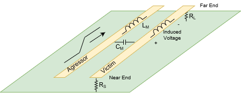
As the rising edge begins to propagate down the aggressor trace, a voltage is induced in the victim that is positive at the near end and negative at the far end. The induced voltage causes a current to flow in the victim based on its characteristic impedance.
Mutual Inductance: Rising edge on aggressor creates voltage on victim with + at near end and – at far end.
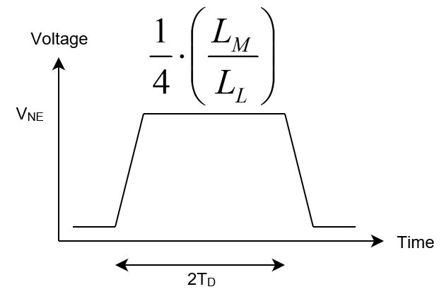
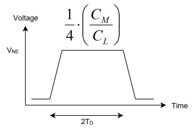
When the signal edge reaches the far end on the aggressor, the coupled wave in the victim reaches its far end and then travels back to the near end. So, crosstalk at the near end persists for a time equal to 2 times the propagation delay of the coupled trace length (round-trip time). The crosstalk ratio (VNE/VA) at the near end is 1/4 * LM/LL.
Crosstalk from Mutual Capacitance
The traces also have mutual capacitance. When a rising edge is driven down the aggressor trace, current flows through mutual capacitance to the victim trace. This current splits on the victim trace with half travelling towards the near end and half travelling towards the far end. The voltage on the victim trace created by this current is positive at both the near and far ends, which is the opposite situation as with mutual inductance.
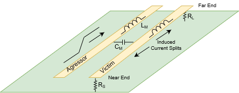
Mutual Capacitance: Rising edge on aggressor causes positive voltage on victim at both near and far ends
As with mutual inductance, near end crosstalk from mutual capacitance persists for a time equal to the round-trip propagation delay of the coupled trace length (2TD). The crosstalk ratio (VNE/VA) at the near end is 1/4 * CM/CL.
Near End Crosstalk from Mutual Capacitance
Total Crosstalk


Where:
- VNE is voltage at the near end
- VA is voltage on the aggressor
- CM is characteristic mutual capacitance
- LM is characteristic mutual inductance
- CL is trace characteristic capacitance (relative to reference planes)
- LL is the trace characteristic inductance
Characteristic means the property as observed by a propagating wavecrest. Characteristic capacitance, for example, is not the same thing as lumped parameter capacitance such as the capacitance of a component.
Near End Crosstalk doesn’t depend on risetime
Far End Crosstalk depends on coupled length and tRISE
FEXT may be zero if the ratios of mutual capacitance per unit length to trace capacitance per unit length and mutual inductance per unit length to trace inductance per unit length are equal. This situation happens when all the field lines are contained within the same dielectric as with a stripline, which is a PCB trace on an inner layer.
FEXT Cancels and is Zero for Stripline (Inner Layer)
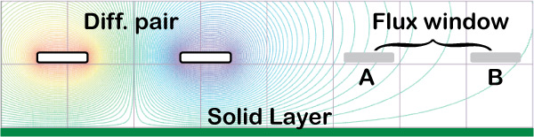
Crosstalk with Differential Pairs
The same issues of mutual inductance and mutual capacitance exist between differential pairs. Although, the crosstalk is smaller due to the cancelling effect of the two signals within the aggressor pair always driving opposite each other, and the cancelling effect in the victim pair due to the receiver subtracting out the crosstalk induced in each intra-pair trace.
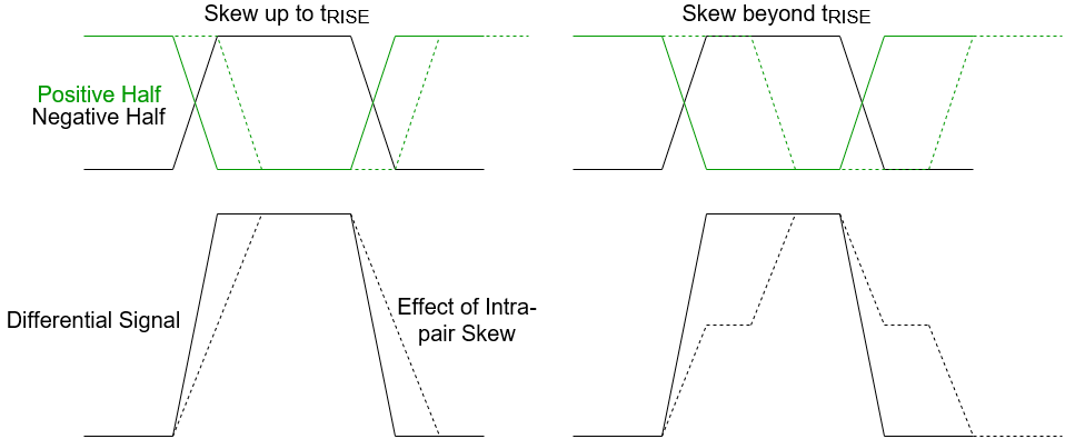
Additionally, differential pairs may suffer from far end crosstalk due to the signals in the two halves of the pair not being perfectly synchronized. Perhaps this phenomenon is not technically crosstalk, but contributes to the far end mess of crosstalk and transmission line reflections to jack up your differential signals.
How to Address Crosstalk
There are several approaches to mitigating crosstalk.
- Spacing – Spread out your traces. Avoid routing traces close together for long distances.
- Route on inner layer – alleviates far end crosstalk from coupling
- Differential Pairs:
- Length match Intra-pair traces
- Space pairs such that the inter-pair spacing is at least 3 times the intra-pair spacing.