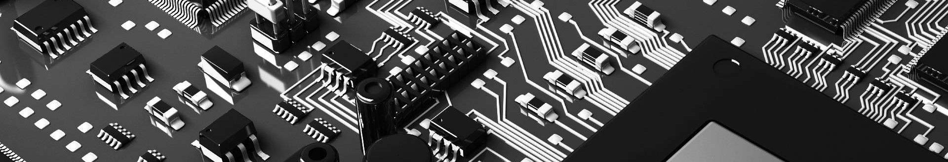
The Serial Peripheral Interface (SPI) Bus is an electrical engineer’s best friend. In its simplest form, it is a point-to-point interface with master/slave relationship. The signals are all uni-directional and point-to-point, which allows for simple series termination for high-speed transmission line operation. It can run at quite a high frequency, with typical devices topping out at 50MHz.
SPI is a serial bus and consists of a minimum of four signals. Data is clocked out in serial form from master to slave on the MOSI line, and data is clocked in in serial form from slave to master on the MISO line. One or more Chip Select (CS_L) signals is implemented to select a particular slave device in multi-slave configurations. And, a clock signal is implemented for synchronous operation of the bus.
Signal Definitions
SCLK – SPI Clock. Driven by the SPI master and received by the SPI slave devices. Single Data Rate Clock with configurable edge polarity (rising or falling).
MOSI – Master Out, Slave In. Data driven from the master to the slave devices. Isn’t that nice, how they named the signal something helpful and unambiguous? UART should take note with its transmit and receive that can be either inputs or outputs, depending on your point of view! Not cool, UART!
MISO – Master In, Slave Out. Data driven from the slave devices to the master.
CS_L – Chip Select (Active-Low). Driven by the master to select an individual slave device.
SPI Bus Characteristics
- Maximum Frequency is not defined. The bus can be driven as fast as your chips and board design can handle.
- 25-50 Mbits/sec data transfers are achievable.
- Simple to implement
- Serial Data
- Point-to-point topology allows implementation of transceivers to convert SPI signalling to RS485, or CAN, or fiber-optic, etc. This is transparent to SPI protocol, and enables long-distance and isolated connections.
Multi-Device Topologies
SPI supports two multi-device topologies, daisy-chain and star. Daisy-chain topology splits the clock to route in parallel to the slaves. But, data remains point-to-point. The MISO of one slave goes to the MOSI of another, chaining them together. Data for all the devices clocks through all the devices in a chain similar to boundary scan, each device just picks out the data addressed to them. The final device in the chain drives its MISO to the master.
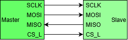
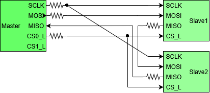
In Star topology all the signals are split and routed to each slave in parallel, except chip select. Multiple chip select are used to select individual slave devices. More devices support this mode than daisy-chain.

High-Speed Design
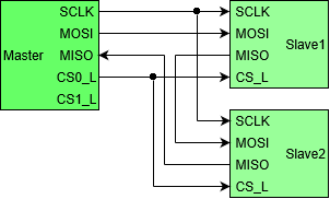
As I mentioned at the beginning, SPI can run at a pretty high frequency, 25-50 MHz is easily achievable. This is because point-to-point connections work great with simple series (source) termination. Just place a small resistor of about 22 Ohms at the source of each signal, and you may want to tune this value by measuring with a scope. The signals drivers are CMOS, and 3.3V, 2.5V, and probably more logic voltage levels are supported.
The Daisy-chain topology can also run fast even though the clock must be split, if there are just two slaves. Since the clock is uni-directional, you can use a termination trick: the bifurcated transmission line. Place series termination (something like 22 Ohms) at the source of the clock, and split the trace after that. Length-match the split trace to each slave. Voila! The bifurcated transmission line. The reflections all cancel each other out when you split a transmission line to two receivers, but it doesn’t work for 3 or more loads, and it doesn’t work for bi-directional signals. You can do the same thing with CS_L.
Bifurcated Transmission Line: Split at the source termination and length match to the two receivers.
One more note on the bifurcated transmission line. Not only is it simple and low-cost, but it is also the clock distribution solution with lowest jitter for two receivers. Jitter is the variability of clock period, and certain applications such as SERDES and Phase Locked Loops require ultra-low jitter. We will cover jitter at some point.
Protocol
SPI Protocol consists of an instruction phase and a data phase.


Next: I2C