A multimeter is an essential tool for electrical engineers and technicians. Basic multimeters can measure voltage, current, and resistance. More advanced multimeters can also measure frequency, capacitance, inductance and diode conductivity. Below is a picture of the Fluke 177 Multimeter.
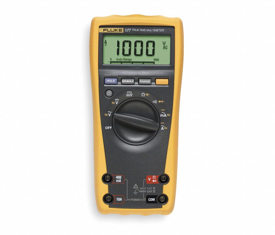
Multimeters come with test probes, typically colored black and red. The black probe plugs in to the COM banana plug receptacle at the bottom. The red probe is plugged in to one of the other 3 banana plug receptacles depending on what you want to measure. Plug it into the V socket to measure voltage, resistance, capacitance and diodes. Plug it into the 400 mA socket to measure current up to 400 mA, and plug into the 10A socket to measure current from 400 mA to 10 A.
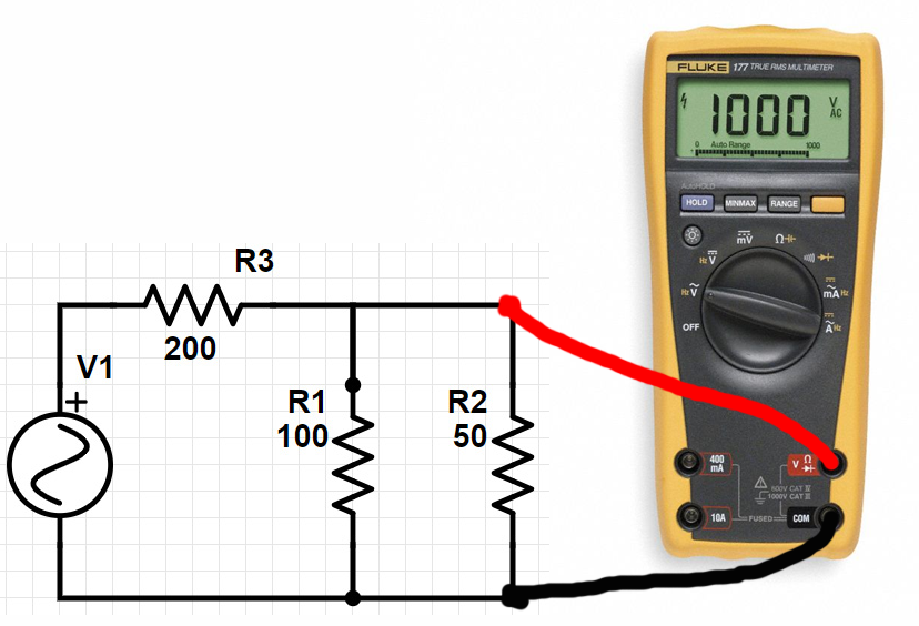
For measuring voltage, resistance, capacitance, and diodes, connect probes to the circuit under test so the multimeter is in parallel with what you are measuring. For example, to measure the resistance of a resistor, connect black probe to one resistor terminal and connect red probe to the other.
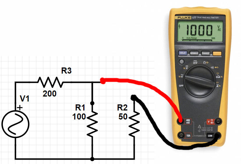
To measure current, connect the multimeter in series with the component you want to measure current through. For example, if you want to measure current through a resistor, disconnect one terminal of the resistor from the circuit, connect one multimeter probe to that terminal, and connect the other multimeter probe to the circuit where the resistor was disconnected. That way the current flowing through the resistor flows through the multimeter.
Regarding polarity, if the voltage of the red probe is higher than the voltage of the black probe, then the measurement of voltage will be positive, else it will be negative. When measuring current, if current flows into the red probe and out the black probe, then the measurement of current will be positive, else negative.
Multimeter Tips:
- The beeping feature for detecting low-impedance connections is extremely useful.
- Since it makes an audible noise, you can keep your eyes on what you are probing and not on the meter.
- Beep out cable conductors to see which pin on one side goes to which on the other.
- On circuit boards, determine what chip pin a signal goes to by having one probe on the signal, then sweep the other probe across the chip pins. It beeps when you hit the pin the signal is connected to.
- When set to measure DC, multimeters measure through a low-pass filter with very low cutoff frequency on the order of 1Hz.
- You can set the meter to measure DC and then measure an AC waveform, and what you will measure is a moving average with time window something like 1 second.
- Can use this knowledge to tell whether a data line is transmitting data or idle.
- Can use this to measure duty cycle of a pulse-width modulated signal. And, more!
- Multimeters typically have a fuse associated with current measurement. It is usually replaceable for those times when you accidentally cause too much current to flow through the meter.
Dial Settings
Primary functions (1:) are active on the dial unless the yellow button is pressed, which switches to secondary functions (2:).
| Setting | Function | Description |
 | Off | Turns off multimeter |
 | 1:AC Voltage 2:Frequency(V) | 1: RMS Magnitude of AC Voltage 2: Frequency of Voltage |
 | 1: DC Voltage 2: Frequency(V) | 1: DC Voltage 2: Frequency of voltage |
 | 1: DC Voltage (mV) | 1: DC Voltage in mV Range |
 | 1: Resistance 2: Capacitance | 1: Resistance 2: Capacitance |
 | 1: Beep Mode 2: Diode Continuity | 1: Beeps for low-resistance connection 2: Voltage of Forward-Biased Diode |
 | 1: AC Current (mV) 2: Frequency(I) | 1: RMS Magnitude of AC Current in mV Range 2: Frequency of Current |
 | 1: AC Current 2: Frequency(I) | 1: RMS Magnitude of AC Current 2: Frequency of Current |
Next: Oscilloscopes