
Op Amps are basic circuit building blocks and can be purchased in a variety of different packages with one or multiple op amps per package. These components are amplifiers, which means that they take an input signal and amplify that signal for the output. The factor that the device amplifies its input by is called its gain. Op Amps in particular have very high gain, essentially infinite input impedance, and low output impedance.
These components can be used in analog applications as scalers and filters, and they can be used in digital applications as comparators. Below is the circuit symbol for an op amp. Vs+ and Vs- are the power supply pins for the device. Positive voltage is applied to Vs+ and negative or ground voltage is applied to Vs-. Vo is the output, V- is the inverting input, and V+ is the non-invertive input.
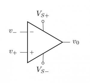
Op Amps use power from the supply pins to amplify the difference between the voltages at the inputs: Vo = K(V+ – V-) where K is some scaling factor. There are two rules to keep in mind for the stand-alone device:
- Inputs are High Impedance. The inputs V+ and V- are very high impedance meaning basically no current flows into those inputs no matter what voltage is applied.
- Output Cannot Exceed Supply. The output voltage Vo can never go higher than Vs+ nor lower than Vs-.
Op Amps are usually configured with some form of feedback allowing them to implement a large number of functions. Positive feedback or no feedback implements a comparator function, and negative feedback implements an analog amplifier and/or frequency filter, depending on what basic components are included in the feedback network. When you look at op amp circuits, it is important to note whether they have positive or negative feedback, because it will determine the way figure out how the circuit works.
Op Amps with No Feedback – Comparators
Op Amps with no feedback are called comparators. The device operates in a fairly simple, straight-forward manner when there is no feedback. When the + input is higher voltage than the – input, the output drives hard up to the voltage of the positive power supply rail. When the – input of the op amp is higher voltage than the + input, the output drives hard down to the power supply return rail (ground or – terminal).
+ Input voltage higher than – input: Output drives to max voltage
– Input voltage higher than + input: Output drives to min voltage
Op Amps with Positive Feedback
Op Amps with positive feedback also behave like comparators, but the positive feedback adds hysteresis.
Op Amps with Negative Feedback
Let’s start by looking at Op Amps with negative feedback. Negative feedback means that there is some component or network of components connected between output and the inverting input (V-). For example, negative feedback can be a resistor connected between output and V-. Negative feedback adds another rule to op amps.
Negative Feedback Drives the Input Voltages Together
An op amp circuit with negative feedback will have close to zero voltage between V+ and V- inputs. In this configuration, you can assume V+ = V- when calculating voltages and currents in the circuit.
An essential parameter of an op amp circuit with negative feedback is its voltage gain. Voltage gain is defined as the output voltage divided by the input voltage. This equation shows how the output is related to the input, Vo = Gain * Vin.
Voltage Gain = Vo/Vin
A circuit’s output signal divided by its input signal in more generally known as the transfer function of that circuit, but in the case of amplifier circuits, it is known as the gain.
Inverting Amplifier
Let’s look at our first op amp circuit below and determine it gain. It has negative feedback provided by Rf, and it is known as an inveting op amp circuit, since the input signal is connected to the inverting op amp input.
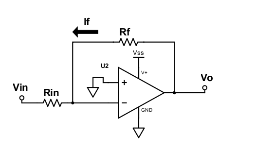
The first step to determining the gain is to note that V- = V+ due to there being negative feedback. Since, V+ is connected to GND (0V), V- = 0V. So, by Ohm’s law:
 , and since the V- input is high impedance, all feedback (If) current flows through Rin to Vin.
 , substitute for If:
 , rearrange:
Gain (Inverting Amplifier) H(s) = 
We used resistors in the circuit above, but Rf and Rin can be generalized to complex impedances using resistors, capacitors and inductors, and just as Ohm’s Law can be generalized to V = Z * I where Z is a complex impedance, so can the gain of a amplifier circuit. Inverting amplifier gain is more generally described as -Zf/Zin where Zf is the total impedance of the component(s) in the feedback network, and Zin is the input impedance.
General Inverting Amplifier Gain H(s) = 
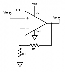
Non-Inverting Amplifier
The non-inverting amplifier also has negative feedback, but the input signal now connects to the V+ input of the Op Amp.
Gain (Non-Inverting Amplifier) H(s) = 
General Non-Inverting Amplifier Gain H(s) = 
Gain is the transfer function for an amplifier circuit.
Op Amp Components
Next: Phase Locked Loop