
Transistors are semiconductor devices that are used to amplify or switch on and off electric signals. There are two main types of transistors: bipolar junction transistors (BJT), and field effect transistors (FET). These two types of transistors are quite different from each other. They both can amplify signals and switch signals on and off, but the way you control them and their behavior is quite different. Transistors are 3-terminal devices, two of these terminals are for the main conductive path through the device, and the 3rd terminal is for controlling that path.
Bipolar Junction Transistors (BJTs)
There are two types of BJTs: PNP and NPN. The ‘P’s and ‘N’s refer to the silicon doping agent used in the fabrication of the transistor, and the salient difference difference to remember is that they have opposite polarity, meaning that current flows in and out the terminals in opposite directions. The terminals of BJTs are called Base (b), Collector (c), and Emitter (e).
B = Base
C = Collector
E = Emitter
BJT Symbols
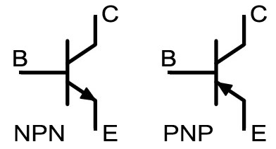
The collector and emitter form the main conductive path, and the base controls that path.
To explain how a BJT works, I am going to start with an NPN. A PNP is the same, but with the directions of current at each terminal reversed. It is easiest to think of BJTs as current controlled devices and to think of that arrow in the symbol as a diode. To turn on an NPN BJT, one needs to put some current into the base. This current flows through the base, through the diode represented by the arrow, and out the emitter. The forward voltage of the base to emitter diode is usually about .7V, so current flowing from base to emitter creates a voltage of .7V from base to emitter (Vbe = .7V). Current flowing into the base also causes current to flow into the collector and out the emitter (current into the base “turns on” the transistor). This current allowed to flow into the collector, Ic, is proportional to the current flowing into the base, Ib, and the constant of proportionality is called beta (β) and is one of the key specifications of a BJT. So, total current flowing out the emitter is Ib + Ic.
One other important aspect of BJTs is the voltage between collector and emitter. There is no particular voltage relationship there, except that there is a minimum voltage, which is typically .2V to .3V from collector to emitter for an NPN, and from emitter to collector for a PNP. This is called VCE,SAT (Collector-Emitter saturation voltage).
To turn off an NPN BJT, just stop putting current into the base. Current will then stop flowing from collector to emitter, or said another way, the conductive path from collector to emitter shuts off.
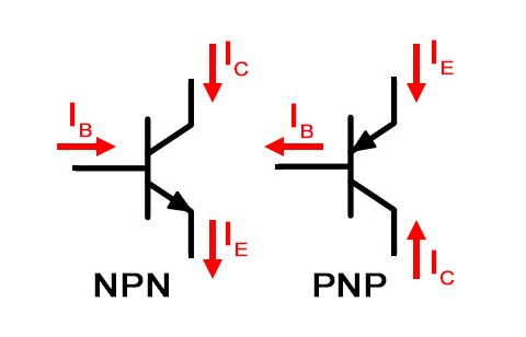
As I said above, PNPs are just like NPNs, except the current flows in opposite directions. To turn on a PNP, pull current out of the base. That current flows to the base from the emitter through the diode represented by the arrow and a voltage of about .7V forms from emitter to base. Current flowing out of the base from the emitter causes current to flow out of the collector from the emitter. The current that is induced to flow from emitter to collector is propotional to the current flowing out of the base, and the constant of proportionality is β.
Common BJT Equations
IE = IB + IC; Emitter current is equal to base current plus collector current.
IC = β * IB; Collector current is equal to the transistor’s beta times the base current.
VCE,SAT = ~ +/-.3V; When turned on, the minimum voltage (saturation voltage) from collector to emitter is about +.3V for NPN and -.3V for PNP.
- Note that Vce will not necessarily be this low, just that it will not go lower no matter how much more collector current flows…the device has been saturated.
VBE = ~ +/-.7V; When turned on, the voltage from base to emitter is about +.7V for NPN and -.7V for PNP.
BJT as an Amplifier
To use a BJT as an amplifier, one utilizes the relationship between collector current and base current. The beta of a transistor is typically between 50 and 200, so a current put into the base will be amplified in the collector current by the beta. If you want to amplify voltage instead of current, simply use resistors to convert voltage to current by Ohm’s law. One important thing to know is that for most BJT’s beta is not a precise specification. It varies alot with temperature for one thing. So, there are some tricks you need to use for a practical implementation of a BJT used as a precise amplifier.
I have to be honest that I have not had to implement a BJT for this purpose in my career, and I no longer remember those tricks from college, so I’m going to stop discussing the use of BJTs as amplifiers at this point.
BJT as a Switch
A BJT transitor can be used like a switch by driving it between complete saturation and completely off. To drive an NPN BJT into saturation, drive enough current into the base such VCE_SAT gets down to .2 – .3V, and then drive more to ensure margin. Consider the circuit below showing an NPN BJT transistor driving a resistor, for example.
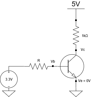
The question is what value of R will ensure the 3.3V supply drives the transistor into saturation, which we will define as VCE_SAT = .3V. Remember that: collector current = β * base current. I’m going to tell you a good rule of thumb for BJT saturation. Beta typically varies a lot with temperature, so be careful to consider worst case, but you do not really need to know the actual beta of the transistor. The lowest values of beta are perhaps about 50, so just assume a beta of 10. Design around a beta of 10 for saturation, and you should have plenty of margin.
Rule of Thumb: Assume Beta = 10 for Saturation Calculations
Process:
- Determine Ic from the components in the conductive path from collector to emitter
- Calculate Ib from Ib = Ic / β
- Determine R from the components in the conductive path from base to emitter.


Remember that Vb is about .7V above Ve in an NPN BJT transistor.

R should be 5532 or less to ensure the transistor goes into saturation. 4.7K is a common, standard value, so that would be my choice. And, there should be plenty of margin to allow a loose tolerance of 5%.