
Circuits
A circuit is a conductive closed-loop path or paths through which current flows. Current can flow in a open-loop path, from one point to another, but only transiently, like in the event of an electrostatic discharge or the firing of a neuron. Sustained current flow requires closed-loop paths. Circuits consist of conductors and electronic components (passive, active, or semiconductor), and the connection points between components are called nodes or junctions. Let’s review and summarize electronic component circuit symbols.
Summary of Circuit Component Symbols
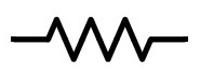
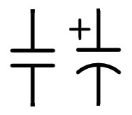
Passive Component Symbols


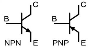
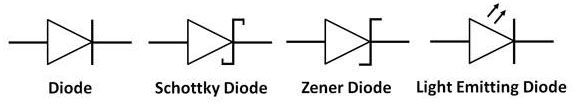
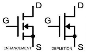
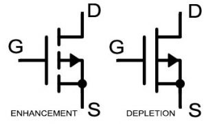
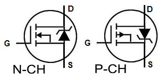
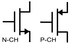
Semiconductor Symbols
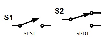
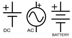
Active (Power Supply) Circuit Symbols

Note in the preceeding table switch symbols have designations SPST and SPDT. In these common acronyms for switch types, S means single, D means double, P means pole, and T means throw. Pole refers to the fixed connection point for a switch, and throw refers to the contact that is connected to the pole when the switch is closed and disconnected from the pole when the switch is open. So, SPDT means a switch with a single pole and with two possible connection points (throws). The SPDT switch can connect the pole to contact #1 or to contact #2.
Ground Reference Voltage
At this point I would like to talk about ground. Voltage is an electric potential difference and is therefore relative by nature. When a circuit node is determined to be at 5 Volts, that voltage is relative to a reference node. That is what ground is: it is a voltage reference node for circuits to which we assign the value of 0V. Circuits do not have to have a ground node, but the analysis is simplified by assigning 0V to one of the circuit nodes. The origin of the term ground is literally “the ground” as in the earth. This may be because power companies reference the voltage they provide to buildings to the voltage of the earth, and they use the earth to conduct the return current in their power distribution circuits. Also, the earth provides a vast sink for charge meaning that a whole bunch of charge can be dumped into the earth without really affecting its voltage.
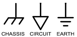
You may notice in the table above that there are several different ground symbols, and there are more even than are shown there. These different symbols are needed, because although ground is defined as the 0V reference node for a circuit, the grounds of different circuits may have voltage differences between them. For example, your computer has circuit boards with ground planes. These are big wide layers of copper and used as the 0V voltage reference for all circuits on those boards. The power supply for your computer has a connection to the ground planes on its output, but on the input to the supply, it probably has a connection to earth ground, which literally connects to the earth around your house. That power supply may or may not have a direct connection from the circuit board ground planes to earth ground, and even if it does, the wires do not have zero resistance, so with enough current flowing to earth, the ground planes will be at a higher voltage than earth ground. So, not all grounds are at the same voltage relative to each other, and we need the different symbols to differentiate.
Circuit Example
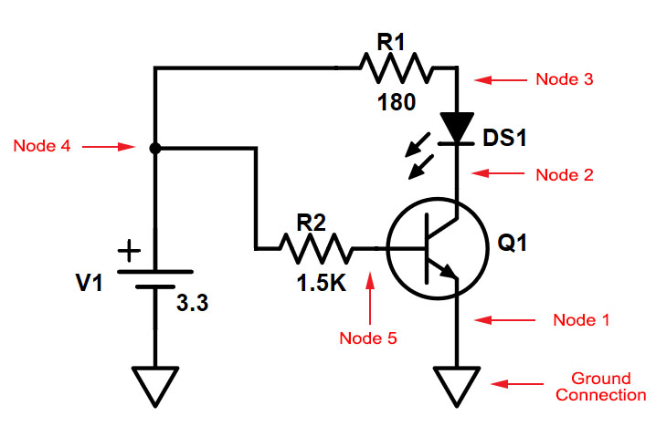
Below is a drawing of an example circuit. This circuit contains 5 components: DC voltage supply V1, two resistors R1 and R2, an LED DS1, and an NPN BJT transistor Q1. The connections between these components form the nodes, which are labelled. Node 1 has the circuit ground symbol connected to it, so it is considered to be at 0V voltage. Note that the negative terminal of the voltage supply also has the circuit ground symbol connected to it, so that terminal is also considered to be connected to node 1. All points connected to the same ground are part of the same node, and current flows freely between these points.
This circuit does make a closed loop. Current flows out of the positive terminal of the voltage supply, flows through the components, and returns through the ground node to the negative terminal of the power supply. Current is often refered to a forward current, which is the current flowing out of the power supply and through the components, and return current, which is the current flowing back to the power supply.
DC, AC, and Transient Circuit Analysis
Circuit analysis basically boils down to determining the voltage at each node and the current through each component of a circuit. But, there are different types of circuit analysis, with the main forms being DC analysis, AC analysis, and transient analysis. DC analysis means analysis that either does not take time into account or considers just one instant of time. And, if DC analysis is considering one instant of time, that instant is not during a transitory period such as being powered on, but during steady-state operation, which is the long term groove of normal operation the circuit gets into.
AC analysis involves determining the effects of driving a circuit with time-dependent functions. Actually, in practice we deal with and think about frequency rather than time when conducting AC analysis, because the math and the intellectual grasp is easier with frequency. With AC analysis, we are looking at the frequency repsonse of a circuit: what band of frequencies get filtered out, what frequency components of the spectrum of my driving signal get passed through, what frequencies cause resonance. AC analysis is also concerned only with the steady-state operation of circuits. Note that AC analysis does not make sense for the preceding example circuit, because it has only a DC power supply, and ideal resistors, LED, and BJT whose relationship between voltage and current are time invariant. For AC analysis to make sense, you need a circuit with inductors and/or capacitors or a power supply with a time-dependent function such as a sine wave.
Transient analysis determines how circuits react to transitory events such as being powered on, or seeing what happeens when a signal first arrives, or being subjected to an electro-static discharge. Transient is the opposite of steady-state; it is the transition period when circuits change from one steady-state to another. Transient analysis is also used to analyze distributed element (transmission line) effects, which we will talk about in depth later on.
Next: Kirchhoff’s Laws