
Léon Charles Thévenin was a French Telegraph engineer living from 1857 – 1926, and Edward Lawry Norton was a Bell Labs engineer living from 1898 – 1983 and they developed helpful tools for us electrical engineers: Thévenin’s Theorem and Norton’s Theorem.

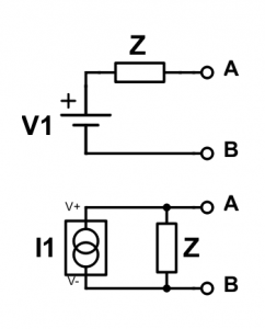
These theorems state that any linear circuit containing one or more voltage or current sources and any number of resistors, capacitors, and inductors can be exactly represented by a voltage source in series with an impedence element or by a current source in parallel with an impedance element. Thevenin’s Theorem describes the voltage form, and Noton’s Theorem describes the current form of the equivalent circuit.
Thévenin and Norton Equivalent Circuits:
This is a powerful tool for simplifying complex circuits, and it is also a powerful concept to imagine that any linear circuit can be exactly represented by the Thevenin and Norton Equivalent circuit. But, what is meant by a “linear” circuit? A linear circuit is one whose impedances (resistance, inductance, and capacitance) do not change due to voltage, current, or time. An example of a non-linear circuit is one containing a transistor. The resistance from drain to source of a MOSFET changes depending on the voltage applied to the gate, so non-linear. A mechanical switch is also a non-linear device.
Linear Circuit: Impedances do not change due to voltage, current or time
Finding the Thevenin Equivalent Circuit
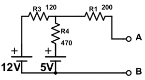
I’ll start by showing you how to find the Thévenin equivalent circuit (voltage source equivalent circuit) for the example below. Choose the point of view for the Thévenin equivalent, because the quivalent circuit can be determined between any two nodes in the circuit. We will find the equivalent circuit between nodes A and B for this example.
1st Step: Nullify Voltage & Current Sources
The first step is to short-circuit any voltage sources and open-circuit any current sources. In other words, nullify all sources with voltage sources going to 0V and current sources going to 0A.
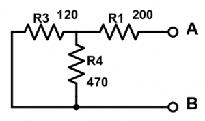
2nd Step: Combine Impedances
Second, combine the impedances using parallel and series combinations. R3 is in parallel with R4:

The parallel combination of R3 and R4 is then in series with R1:

This is the Thévenin equivalent impedance, Z, and that value is the same for the impedance Z in the Norton Equivalent circuit (current source equivalent circuit).
3rd Step: Determine the Thévenin Voltage Source
Third, determine the Thévenin equivalent Voltage source by putting the sources back in, and calculating the open-circuit voltage across nodes A and B.
Thévenin Voltage = Open-Circuit Voltage across A and B
By inspection, note that no current flows through R1 due to the open-cricuit between A and B. Because no current flows through R1, the voltage at A is equal to the node where R3 and R4 connect, which is a voltage divider.

This is the voltage divider voltage, which is the voltage of the node where R3 and R4 connect relative to the positive node of the 5V supply. To get the voltage of that node relative to node B, you must add 5V for that voltage source.

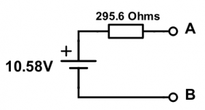
This is the Thevenin equivalent voltage. We have our equivalent circuit:
Finding the Norton Equivalent Circuit
The impedance is the same in both Thevenin and Norton Equivalent Circuits, so we already determined Z and now just need to determine the current source. The Norton Equivalent current source is the short circuit current flowing between the nodes of interest, which are A and B for this example. Add a short circuit connection between A and B and calculate the current flowing through that connection. I updated the circuit with arrows indicating the flow of current (just guesses at direction, which is fine as long as I choose a direction and stick to it) and added voltage node Vc.
Norton Current = Short-Circuit Current between A and B
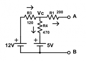
For convenience, let’s set node B to be ground potential. We can do this, because voltage is relative. The current flowing from A to B is then:

To find Vc, we need to employ KCL at Vc. The sum of the currents going into the node equal the sum of the currents going out of the node.

Now, do Ohm’s law for each current:
 , rearrange:
 , rearrange:
 , rearrange:
Substitute into KCL:  , change around:
 , reduce:

Plug this into I = Vc/R_1:

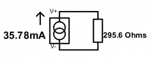
This is the value of the Norton Equivalent current source. We now have the Norton Equivalent Circuit.
Let’s review the steps to determine the Thevenin and Norton Equivalent Circuits.
Steps to Find the Thevenin and Norton Equivalent Circuits
- Choose the two nodes from whose point of view you want to calculate the equivalent circuit.
- Nullify all power sources (short voltage sources and open current sources)
- Combine impedances using parallel and series reduction combinations. The result is the Thevenin and Norton Equivalent Impedance.
- Put the sources back in, and calculate the open circuit voltage across your two nodes, which is the Thevenin Voltage Source
- Calculate the short circuit current flowing between your nodes, which is the Norton Current Source.
One final important note is that Ohm’s law applies to the equivalent circuits. So, a much quicker way to calculate the Norton current in the example above would have been to use Ohm’s Law. Norton Current = Thevenin Voltage / Equivalent Impedance = 10.58V / 295.6 Ohms = 35.78 mA. BAM!
Thevenin Voltage = Norton Current * Equivalent Impedance
Next: Filters