Electrical Characterization is a set of measurements that electrical engineers will perform to validate signal quality on a PCA. This test involves measuring the interconnect signals and buses with an oscilloscope to verify that they meet component specifications, and it should be performed early in prototype phases, just after bringup. The early time frame make this test difficult to perform, since often firmware is not yet developed, and you have to use development probes and tricks to exercise the interconnect signals so that you can measure them. But, it is an important test as you can find design mistakes, marginal signals and other issues that can cause a lot of wasted time and money down the road.
Some datasheets are massive with many specs, so what does electrical characterization need to cover? It needs to cover your design and the interfaces between your design and the components. Electrical characterization does not need to cover the components, themselves. It does not need to cover specs that relate only to the internal workings of the component and nothing to do with your design. We can’t test everything and need to trust our suppliers to provide good components that do what they claim. So, electrical characterization for a PCA should cover digital interconnects between components, analog circuits, and power to components.
Create an Electrical Characterization Plan. You can use the time while your board is being fabricated to write the plan and have it ready to go when you receive the boards. In your plan, list out each digital interface and analog circuit, list the measurements you need to perform to verify component specs, and paste those specs right in your plan document. Then, when you make the measurements, put screen shots in the report. And, finally include a summary where you list each measurement against relevant specs and declare the signal or bus a pass or not. I can’t tell you how many times I have gone back to old electrical characterization reports to check what some signal is doing or looks like in reference to some current issue. Do the right thing and document!
To aid the documentation, be sure to label the measurement channels in your scope and add screen annotations so that you can look at the screen shot images years later and know what they signify and under what conditions. Something that often happens to me is that I forget to change screen annotations in subsequent measurements and don’t realize the mistake until after I have undone the probe connections, and the old annotations are incorrect or confusing. Get those screen shots right into some image editing program and change the annotation and overwrite the file. It is crucial that the scope screen shots are accurate and contain description.
Electrical Characterization Report
- List all digital interfaces and analog circuits
- List all relevant specs for each interface/circuit; get specs from component datasheets.
- List measurements that must be made to check the specs
- Paste scope screenshots for each measurement
- Include a summary for each interface/circuit listing measured values next to specified values and declare each a pass or fail.
Power Measurements
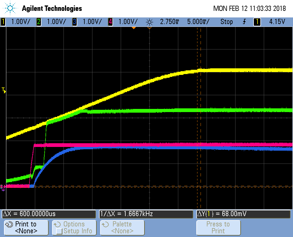
Power rail and regulator measurements are an important part of electrical characterization. The output rail of each regulator should be measured for a start-up event, during steady-state, and during a shut-down event. Also, for systems with multiple power rails, turn-on and off sequencing of rails may need to be checked.
Regulators:
- Start-up Event:
- Verify monotonic edge – dips of rails while they turn on can cause chips to get partially reset causing problems. Dips are caused by large downstream loads turning on.
- Check voltage overshoot
- Check turn-on time
- Cover all the various turn-on methods: apply AC power, plug in DC cord, push power button, etc.
- Check any hot plugged power rails; check for overshoot and ringing
- Steady-State:
- Check average voltage
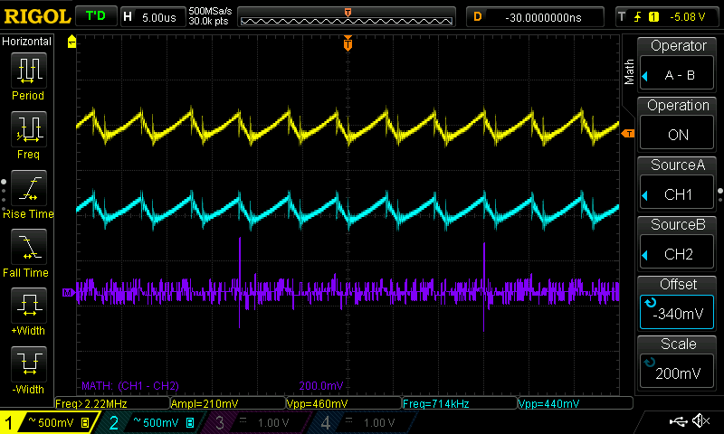
- Check ripple voltage for switching regulators
- Check ripple current for switching regulators ; verify output cap can handle the ripple
- Measure load current under idle and heavy-use conditions; verify regulator and inductor can handle the max load current plus ripple.
- Measure noise
- Measure transient load response. Use electronic load to apply a step load and measure the output rail to see if the transient load response oscillates. This checks the stability of the regulator.
- Shut-down Event:
- Verify rails decay to 0V
- Measure turn-off time
- Cover all the different turn off methods: pull the plug, push power button, etc.
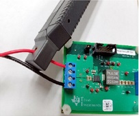
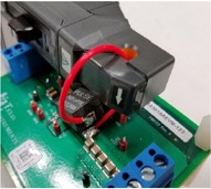
For measuring current, use a current probe for your oscilloscope. This uses a Hall-effect sensor to measure the magnetic field and extrapolate to a measurement of the current flowing through the hole in the probe. For measuring ripple current in power regulators, one technique is to list one pad of the inductor and solder in a loop of wire, so you can measure the current flowing through the inductor. Keep the loop of wire short to not affect the signal.
Rail Sequencing
Measure the power rails together during turn on and turn off. Think about the following.
- Turn-On:
- If a rail dips, look to see if another rail turns on at that same time. this may be a clue to the reason for the dip.
- Think about interfaces and circuits and chips that involve more than one power rail:
- Consider if there is a potential for latch-up (driving signals into unpowered chips) due to the rail sequencing.
- Check if any of the chips have special sequencing requirements and whether those are met.
- Consider the possibility of incorrect logic states during start-up occurring because of the rail sequence and if that might cause a problem like getting stuck in reset.
- Turn-Off:
- Check if some rails appear to not decay normally. Sometimes you can see that a rail’s decay is held up by some other rail indicating a connection, which may be current leakage
Scope Probing
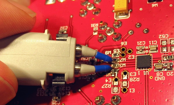
You need to use good probes and good probing techniques. Even if you are checking some simple, low-frequency signal, it is good to see an accurate picture of noise on the signal and spikes and other issues. Poor probes and probing solutions can filter out things that are actually present, and they can add signal issues that are not really there. And, they can load down the signal with capacitance that distorts it. See my section on oscilloscopes to learn more about different probes and probing techniques.
High-Speed Digital Measurements
With high-speed digital measurements, you need to check not only ordinary digital logic specs like VIL, VIH, Setup time, Hold Time, etc., but you also need to check transmission line effects such as reflections and cross-talk. So, you need to use an active probe whose bandwidth is significantly higher than the high-frequency components associated with the signal edges. Remember that digital signals are like square waves, not sinusoids, so they are are not a single frequency but collections of frequency components, and the signal edges and corners are determined by the high-frequency components. (See my section of Fourier Analysis: https://practicalee.com/superposition/.) A good rule of thumb is you need a probe with bandwith at least 10x the fundamental frequency of the digital signal you are measuring. For Example, if you are measuring a 10MHz clock for a SPI bus, you need a probing solution that covers at least up to 100MHz.
You also need to get your probe tip close to the signal measurement point. You can’t solder a long wire to the board and then clip a probe on the end of that for high-speed digital measurements. You need to get your probe close enough that the stub introduced by its connection does not exhibit transmission line effects. The stub should be less than 1/6th the length of the physical distance occupied by the signal rise or fall time, whichever is faster. For example, if rise time is 1ns and propagation delay is 150ps/inch, then rise time occupies about 6 inches. So, the stub introduced by your probe connection should be less than 1 inch.
Next: Margin Test