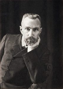
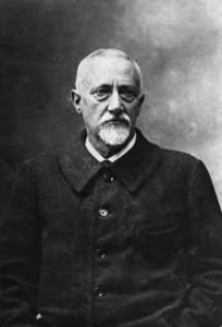
The piezoelectric effect is an ability of some materials to generate electric charge when mechanical stress is applied, and conversely to distort shape when an electric field is applied. This effect was discovered by Jacques and Pierre Curie in 1880. Pierre Curie was the husband of the physicist Marie Curie who did pioneering research into radioactivity and was the first woman to win a Nobel Prize.
Quartz crystals are piezoelectric material and oscillate at a precise frequency when stimulated with the proper voltage waveform. The crystal distorts when voltage is applied, and when the electric field is removed, returns to its previous shape and generates an electric field that can produce a voltage potential. Crystals are used to generate clock signals for synchronous digital logic, and used in many other applications.
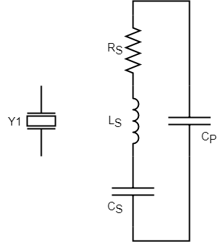
Below is the circuit symbol used for crystals, and the circuit model of a crystal. S means series and P means parallel. In schematics we use Y or XTAL letters for crystal reference designators.
Implementing Crystals
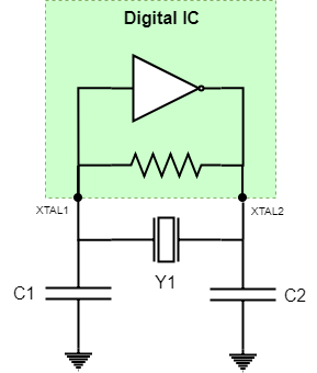
Usually crystals are implemented in what’s called a Pierce oscillator, where each crystal terminal is connected to an XTAL input pin on the digital chip, and a capacitor is also connected between each crystal terminal and ground. Inside the digital IC is the excitation circuit, which consists of an inverter driving a resistor load. The capacitors to ground are what provide the timing elements to tune the inverter circuit to put out an oscillatory voltage waveform that resonates with the crystal’s fundamental frequency or harmonic thereof.
When implementing a crystal in Pierce Oscillator configuration, you need to determine the value of C1 and C2 based on the crystal’s load capacitance (CL) specification. The values for C1 and C2 are typically very low (on the order of 10pF), so the trace capacitance to the digital IC and its pin capacitance for the XTAL pins needs to be taken into account, because they are also on that order of value. Total up the trace capacitance and pin capacitance for both traces and both pins, and this is called stray capacitance CSTRAY. Pins are typically 1-2pF, trace depends on how long, but if you keep the trace short it may be another 1-2pF. So, a quick rule of thumb is to go with 6pF for stray capacitance. C1 and C2 are usually chosen to have the same value, in which case the formula below can be used.
Rule of Thumb: CSTRAY = 6pF if traces are short.
CL = Crystal’s load capacitance specification from datasheet

With the value of C1 and C2 determined look for the next closest standard value of capacitor and implement that one. If the capacitor values are off a bit, the result is that the crystal frequency will be offset a bit. Usually this is not a problem such as for a microcontroller clock, but some applications such as keeping accurate time require a very accurate frequency.
Because the capacitance that tunes the crystal circuit is so low, the capacitance of scope probes, even active probes, is enough to alter the signals.
Example
You are implementing a microcontroller that wants a 24MHz crystal. You identify a crystal that you like with CL spec of 12pF.
C1 = C2 = 2 * 12pF – 2 * 6pF = 12pF.
Implement 12pF caps.
Crystal Oscillators
Crystal oscillators are components that contain the crystal with piezoelectric effect, but also contains the oscillator circuitry, and provides an output clock signal belonging to a particular logic family. So, you can get crystal oscillators that output a CMOS square wave, or LVTTL, or LVDS, and they come in a variety of frequencies. As you can imagine some frequencies are more common than others.
Here is a helpful list of common frequencies: https://www.vectron.com/products/std_freq.htm